Reduced mechanical case study, thermal references and traceable process evidence.
Process demonstration—unvalidated engineering estimates. Global force/moment equilibrium, local rod-contact stress and the original maximum 5% DNBR penalty are not established.
Original request and where it came from
This study began with an engineering challenge proposed by Thomas Rambach (@cadtoolbox) in replies on X to @burhop. The project owner pasted the posts into the Wright working conversation. Wright organized that supplied brief into requirements, identified missing model inputs, and prepared an analysis and verification process.
Source provenance: user-supplied transcription of the posts. Original post URLs and absolute timestamps were not supplied; the social-media source has not been independently authenticated. The excerpt below preserves the supplied wording. Later assumptions and verification criteria were added during this project and are identified separately.
“Problem: Analyze a 5×5 rod-bundle segment with one mid-span spacer grid. One peripheral rod is bowed toward an adjacent rod, reducing the nominal 3.1 mm wall-to-wall gap.”
“Task 1 – Mechanical: For 50 %, 80 %, and 100 % gap closure, calculate lateral force through the grid springs/dimples and added bending stress in the cladding.”
“Also estimate residual spring force at end-of-life using a simple relaxation model or published irradiation data.”
Requirements extracted from the supplied posts
Requested item
Supplied requirement
Where to examine it
Geometry and material
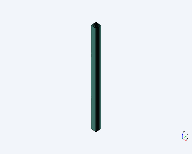
5 × 5 segment of a 17 × 17 PWR assembly; one mid-span grid; one peripheral bowed rod; 9.5 mm OD; 12.6 mm pitch; 3.1 mm nominal gap; Zircaloy-4 cladding.
50%, 80%, 100% gap closure; lateral spring/dimple force and added cladding bending stress; support stiffness 50 N/mm as fabricated and 20 N/mm after irradiation.
SUPPLIED These numbers define the requested problem; they are not measurements collected by Wright. The 5% limit is the proposer’s requested comparison criterion, not a universal reactor acceptance limit.
How the brief became this demonstration
The original posts supplied the problem and principal quantities, but not a complete geometry, support/contact model, irradiation history or applicable CHF method.
The project added matched 0% closure reference cases, requirements-to-evidence checks, and A/B/C engineer review checkpoints. V01–V20 are the project’s verification plan, not additional quotations from the posts.
The user requested a documented reference material/history for the residual-force estimate, then explicitly authorized a provisional process demonstration using existing tools and attributed substitutes where full capability was unavailable.
Checkpoint A approved the reduced-model assumptions. The pilot exposed three failed force-screening checks. Checkpoint B approved continued demonstration reporting with those failures retained.
Eight native mechanical cases completed. Checkpoint C approved the demonstration report and public package. None of those approvals establishes physical design validity.
The proposed problem connects the mechanical position and support of a fuel rod with its ability to reject heat to the coolant. The original brief identifies three concerns: a closing gap can redistribute coolant, increase grid-to-rod fretting risk, and reduce thermal margin. An engineer needs to understand their interaction before judging whether a particular bow is acceptable.
Loads and cladding stress
How much additional load does the bowed rod apply to its support, and what bending stress accompanies that deformation? The force and stress results address a reduced version of this question; they do not resolve individual contacts or wear.
Support over service exposure
Does the spring retain enough preload to provide its intended support? Spring stiffness and retained preload are different quantities. Comparing 50 and 20 N/mm alone does not answer the end-of-life preload question.
Cooling margin
What happens to local heat removal when the flow passage changes? A whole-bundle average outlet temperature cannot by itself establish the thermal condition at the most limiting rod location.
DNBR means departure from nucleate boiling ratio: the heat flux associated with DNB divided by the actual local rod heat flux. DNB is a deterioration in heat transfer associated with insulating vapor at the rod surface. These definitions explain why local conditions matter. See the NRC definitions of DNBR and DNB.
The intended engineering decision was whether the specified gap closures and support states produce acceptable mechanical and thermal penalties. The demonstrated outcome is a traceable reduced mechanical comparison and explicitly limited thermal/material estimates. The original acceptance question remains open.
For an engineer reviewing Wright, the useful evidence is the connected handoff from requirements and assumptions to existing-tool calculations, numerical checks, a recorded exception and a report that preserves unresolved requirements. A completed process is not a substitute for a validated engineering answer.
How to read the evidence
Each label describes where information came from. Color is reinforced by text so the distinction does not depend on color vision.
SUPPLIED INPUT A value from the original brief; not independently measured here.
ASSUMPTION / SCENARIO An analyst-selected value or simplification needed to run this demonstration. It is not measured or automatically conservative.
NATIVE CALCULATION — PROVISIONAL INPUTS An actual tool result, conditional on the stated model and assumptions.
PUBLISHED REFERENCE Data or a fitted relationship from another experiment, with its source conditions retained.
TRANSFERRED ESTIMATE — UNVALIDATED A reference applied to an assumed study scenario; applicability to this design is not demonstrated.
NOT ESTABLISHED The available evidence does not support a result or acceptance decision.
A labelled estimate is not a verified fact. The register below gives each major assumption, why it was needed, which result it affects, and what evidence would replace it. Approval to use an assumption in a demonstration does not verify that assumption. Numerical digits describe solver output, not demonstrated physical accuracy.
Assumptions and their consequences
These entries are the principal assumptions affecting interpretation of the reported numbers. They are not a claim that all uncertainties have been quantified. The linked basis contains the complete retained model definition; older source records retain their original proposal/review dates.
ASSUMPTION / TRANSFER · M1
Span and tube wall
Adopted basis
1000 mm span; 0.57 mm wall thickness.
Why it was used
Neither was supplied. These are explicit provisional dimensions for a solvable pipe-beam model; no actual assembly drawing establishes them.
Effect on interpretation
Bending response depends on span and section stiffness. The stress values cannot be transferred to an unknown real span/wall.
Evidence needed to replace it
Obtain the actual unsupported span, wall dimensions and tolerances.
E = 77,420.0375 MPa; ν = 0.383780271; pinned lateral ends, planar restraint and torsional datum.
Why it was used
A retained provisional Zircaloy-4 material card at 573.15 K and idealized supports define the reduced calculation. These are not measured properties or demonstrated real-grid constraints.
Effect on interpretation
Stress depends on elasticity and boundary conditions. Pressure, pellet interaction, creep and thermal gradients are omitted.
Evidence needed to replace it
Confirm material state, temperature and actual support constraints; include relevant omitted loads.
Supplied 50/20 N/mm are interpreted as one effective, zero-preload bilateral midpoint spring; closure is imposed at that point.
Why it was used
The brief did not define per-contact stiffness, preload, clearance or support geometry. The effective spring permits an incremental comparison.
Effect on interpretation
Force follows k × relative displacement. At equal imposed closure the two stiffness states have matching beam stress by model construction; this is not a general statement about real fuel rods.
Evidence needed to replace it
Obtain the grid spring/dimple geometry, preload, clearance, stiffness definition and actual bow-loading mechanism.
16-rod HTRF references used for a 25-rod problem; published 85% series used as a labelled proxy for requested 80%.
Why it was used
An applicable study CHF/DNBR prediction was unavailable in the demonstrated toolchain. Published source conditions and both contact arrangements are retained instead.
Effect on interpretation
Source geometry, pressure, inlet temperature and mass flux differ. Reference CHF divided by assumed study heat flux is an illustrative index, never study DNBR or evidence of a ≤5% penalty.
Evidence needed to replace it
Establish an applicable validated method and matched conditions before claiming a study thermal penalty.
The user selected a documented reference history because the actual spring alloy and service history were not supplied. The cited test is not this PWR grid spring.
Effect on interpretation
The conditional 2.511 N estimate uses a published retention fit and assumed preload. “End of life” means this selected reference exposure endpoint, not an actual PWR service lifetime.
Evidence needed to replace it
Confirm alloy, treatment, spring form, initial preload, spectrum, temperature and exposure history; establish transfer applicability.
FAILED VERIFICATION — NOT AN ASSUMPTION The three original force-screening failures are observed test outcomes. Checkpoint B permitted a demonstration to proceed with global equilibrium unresolved; it did not justify the failures away as assumptions.
Problem and analysis basis
A peripheral rod in a 5 × 5 fuel-rod segment bows toward its neighbor. The requested comparison covers 0%, 50%, 80% and 100% closure of the nominal 3.1 mm gap, with effective spacer support stiffnesses of 50 and 20 N/mm.
Supplied inputs: 9.5 mm rod outside diameter, 12.6 mm pitch, 15.5 MPa coolant pressure, 290 °C inlet temperature, 3000 kg/(m²·s) mass flux and 25 kW/m bowed-rod linear power.
ASSUMED MODEL · M1–M4
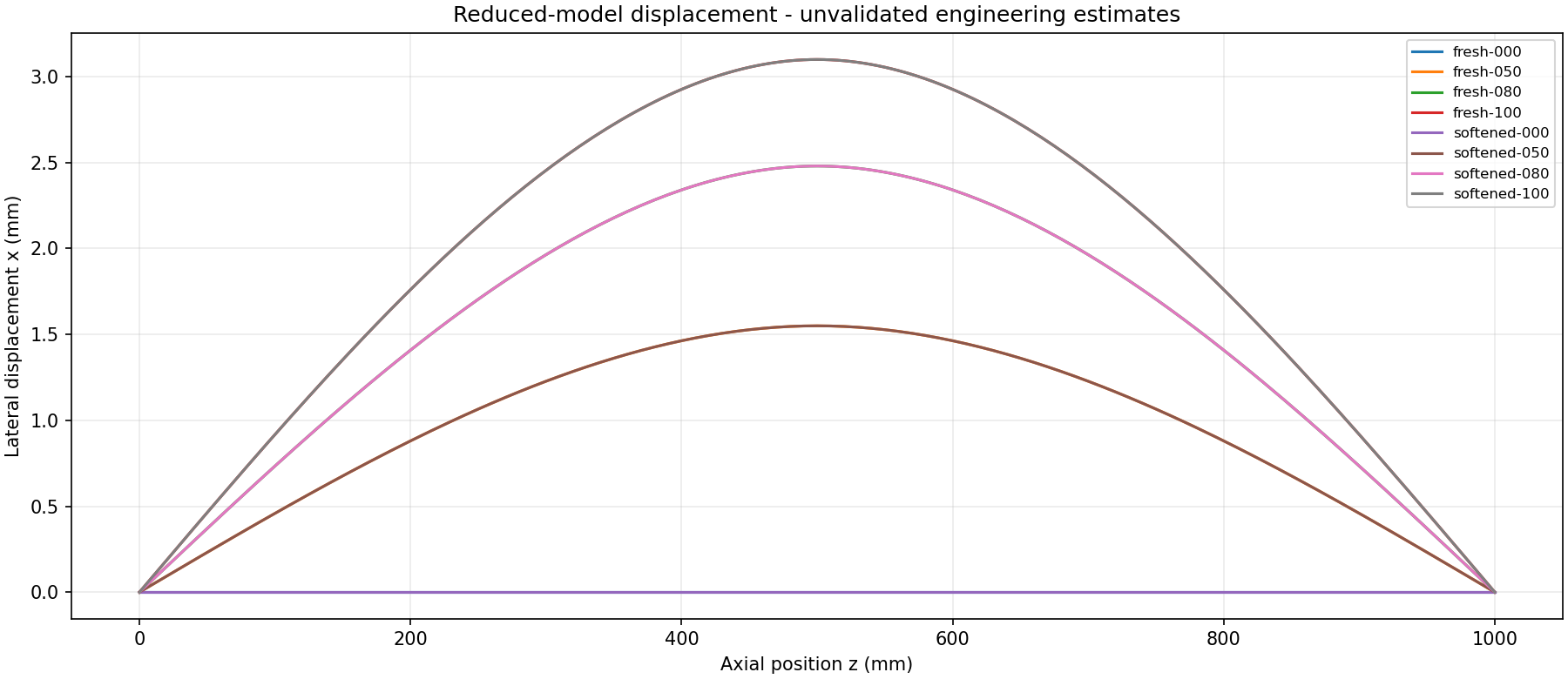
The provisional mechanical model is a 1000 mm pinned hollow beam, with 0.57 mm wall, elastic modulus 77,420 MPa and Poisson ratio 0.38378. A zero-preload midpoint spring and imposed lateral displacement represent incremental bow/support response. The standard mesh has 100 B32R elements; pilot meshes use 50 and 200.
No individual spring/dimple contacts, rod-contact pressure, pellet interaction, pressure stress, irradiation creep or local coolant redistribution are resolved. See the analysis basis, input tables and assumptions.
Eight-case mechanical results
NATIVE CALCULATION — PROVISIONAL INPUTS Conditional on assumptions M1–M4. Stress is the paired increment of axial stress at native integration points; it is not a verified outer-surface peak or local contact stress.
Case
Closure %
k N/mm
Gap mm
Spring force N
Added axial stress MPa
fresh-000
0
50
3.100
0.000
0.00000
fresh-050
50
50
1.550
77.500
6.40682
fresh-080
80
50
0.620
124.000
10.25092
fresh-100
100
50
0.000
155.000
12.81365
softened-000
0
20
3.100
0.000
0.00000
softened-050
50
20
1.550
31.000
6.40682
softened-080
80
20
0.620
49.600
10.25092
softened-100
100
20
0.000
62.000
12.81365
Native nodal displacements; axial and lateral scales differ. Matching curves overlap because displacement is imposed.
At a fixed closure, the colocated spring changes reaction but not imposed beam deformation. This model consequence does not prove that a real rod's bending stress is independent of grid stiffness.
Thermal and end-of-life estimates
CONDITIONAL ESTIMATE · T1 Retained CoolProp observations give a conditional 307.446 °C bulk outlet temperature for the assumed 1 m heated segment, 63 mm square enclosure and all 25 rods at 25 kW/m. This does not establish local surface temperature or DNBR.
PUBLISHED REFERENCEUNVALIDATED TRANSFER · T2 The thermal comparison uses attributed HTRF experimental references from a different 16-rod bundle. The source's 85% closure series is explicitly a proxy for the requested 80%; both source contact arrangements remain separate. Source pressure, inlet temperature and flow differences are preserved.
TRANSFERRED ESTIMATE · E1–E2 The documented X-750/NRU reference transfer gives 2.511 N from an assumed 5 N initial preload at 6 × 10²⁴ n/m². The 2.161–2.917 N slope-sensitivity range is an assumed scenario, not a confidence interval. This estimate is separate from the zero-preload beam calculation and is not an operating-PWR service-life prediction.
Actual tool contributions
Tool or owner
Contribution
Scope limit
SteveCAD MCP
Retained 25-rod CAD context and measured geometric evidence
The native beam model is not a mesh of this CAD assembly.
CalculiX MCP
Eight actual closure/stiffness cases and two additional pilot meshes
Reduced pipe beam and effective spring; no rod-contact solution.
ParaView MCP
Read native fields, compare cases and plot displacement
Read-only postprocessing; global equilibrium remains unverified.
Conditional whole-bundle energy screen, not local CFD.
Pandoc MCP
Editable DOCX, PDF and standalone HTML from one report source
Document rendering does not establish engineering validity.
Wright runtime and validator
Artifact handoffs, exact-output checks and A/B/C decisions
60 demonstration checks passed; original pilot failures retained.
Process and artifact handoffs
The pilot run preserved three completed meshes and its failed assessment. After the engineer approved the disclosed exception at B, the continuation reused those artifacts, ran the seven missing cases, inspected the eight-case matrix and produced the reports. A separate presentation revision corrected document layout without repeating analysis.
Open the reusable Wright swimlane review at full width. Select an activity to inspect its tool, inputs and recorded evidence. The overview now includes the earlier SteveCAD geometry creation and clearance inspection, clearly separated from the 18-stage analysis continuation. Activity details explain engineering inputs, work performed and results; source files are secondary. The saved analysis-run C state predates final publication approval.
Verification and unresolved requirements
The original pilot assessment recorded 25 passes and 3 failed force-screening checks. The actual 100-to-200-element stress difference was 0.164%. B explicitly accepted continuation with global equilibrium unestablished. The continuation then passed 60 checks in the narrower demonstration-evidence profile; this did not clear the original force requirement or establish physical acceptance.
Original criterion: All supplied quantities and both stiffness states preserved; explicit SI conversion; no silent defaults
Evidence and disposition: Supplied values retained; additional choices explicitly proposed and reviewed. This does not resolve every original physical input.
Original criterion: OD 9.5 mm, pitch 12.6 mm; target minimum gaps 3.1, 1.55, 0.62, 0 mm measured on exported geometry
Evidence and disposition: Check nodal centerline approach against an undeformed neighbor. This is not independent exported 3D surface-gap measurement for all cases.
Original criterion: Incremental force matches declared k times measured relative spring displacement, with preload accounted for separately
Evidence and disposition: Effective-spring force checks passed at all eight cases, with a separately declared zero-load normalization; individual contact forces remain outside scope.
Original criterion: Simple independent straight-beam benchmark matches its exact support/load assumptions
Evidence and disposition: Earlier beam-limit evidence is retained. It does not automatically validate the new pipe-beam case or its physical applicability.
Original criterion: Residual vector force and moment each <=1% of the corresponding total applied/reaction scale
Evidence and disposition: Not established. The pilot RF-sum screening failed in all three meshes. The B exception permits demonstration reporting only; full force and moment equilibrium remains unresolved.
Original criterion: At least three systematically refined discretizations; lateral force and nonsingular section bending stress change <=2% between two finest, with trend inspected
Evidence and disposition: Three meshes completed. The 100-to-200 axial integration-point stress change is 0.164%, below 2% and 5%. This is partial evidence for the original requirement, not contact-stress convergence.
Original criterion: No tensile normal contact force in unilateral contact; action/reaction balance; penetration within an explicitly chosen geometric tolerance
Evidence and disposition: No unilateral rod or individual spring/dimple contact model is executed.
Original criterion: Separate added bending stress, pressure/membrane stress if modeled, local contact stress and total equivalent stress
Evidence and disposition: Report actual global axial integration-point stresses and matching-baseline subtraction. Local contact and pressure stresses are unavailable; no allowable/failure verdict.
Original criterion: Zero exposure retains post-immediate-relaxation force; nonnegative parameters give nonnegative, monotone retention; units invariant
Evidence and disposition: Reuse the documented reference arithmetic and sensitivity evidence. Do not substitute the stiffness ratio for relaxation.
Original criterion: Spring alloy, condition, temperature, exposure, preload and constraint history agree with accepted model or explicit uncertainty treatment
Evidence and disposition: Documented X-750 reference material/history; transfer to the study is explicit and unvalidated.
Original criterion: Integrated steady mass imbalance <=0.1% and energy imbalance <=1%, using defined inlet/outlet/source terms
Evidence and disposition: Reuse the conditional bulk energy calculation and native property observations. No spatial inlet/outlet flux integration or local redistribution result.
Original criterion: At least three spatial resolutions and a time-step study where relevant; key local temperatures, pressure drop and minimum DNBR change <=2% between finest runs
Evidence and disposition: No spatial thermal-hydraulic refinement or time-step convergence campaign for this study.
Original criterion: Compare measured and calculated DNB power/location and other relevant measurements using source-specific uncertainties
Evidence and disposition: Retain published source conditions and measured CHF. No matched study-solver prediction is validated against those measurements.
Original criterion: Correct table units, interpolation at nodes and interior points, explicit out-of-range handling; q'' and CHF evaluated on compatible physical locations
Evidence and disposition: No qualified study CHF calculation. A reference CHF/study-heat-flux scaling index is not DNBR.
Original criterion: Matched reference and bowed minima use the same accepted domain and operating conditions; assess supplied 5% limit with uncertainty
Evidence and disposition: The original 5% DNBR penalty requirement stays visible without an invented compliance value.
Original criterion: Every result uses accepted upstream revisions; changed dependencies invalidate affected results/reviews
Evidence and disposition: Exact saved inputs, native attempts and review subjects retained. A was explicitly approved for both the original basis and corrected encoding. B approved the disclosed force-check exception. The saved analysis snapshot precedes final C review; the later final demonstration package received public-content approval, as recorded on this page. This is not physical engineering acceptance.
Original criterion: Editable/PDF/web report share accepted study revision; public bytes match checkpoint C manifest; no restricted material or execution authority
Evidence and disposition: Editable, PDF and HTML report files are produced from the same source. Final public-content approval was subsequently given and this demonstration package is hosted publicly. The original saved analysis snapshot is retained separately; these presentation changes do not create engineering acceptance.
Start with the original request and assumption register above. The downloads retain the approved numerical report. This website adds explanatory context at the project owner’s request; it does not introduce new calculations or change engineering acceptance.
Published references are attributed rather than presented as simulations of this design. Restricted source documents, credentials, execution controls and approval authority are excluded from this static review package. The package records a demonstration, not approval to operate, manufacture or certify nuclear equipment.